Saturday, May 11, 2019

Mounting the empennage to the tail cone #3

I did not follow the directions and mount the elevators to the HS on the bench like they tell you to.  The only reason I can see they have you do that is to help stabilize the whole mess.  My HS is already mounted to the tailcone and I used straps to help keep it stable.  So now I am going to mount the elevators.

First I need to install the rod end bearings into the elevator spars. 

 I made this tool back when I built the RV-7.  It works like a dream at installing rod end bearings into nutplates.

 Detail of how it is made on the business end.

 The bearing goes in like this.  The way it is made, it puts the pressure on the outside of the bearing and not the ball which can damage these things.

 Get the bearing started in the hole and twist to the desired depth.  Easy peasy!

I installed these exactly per the plans which is 7/8" from the center of the ball hole to the face of the elevator front spar.  To make it easier, add 3/8" to that dimension and measure 1-1/4" from the top of the outside edge of the bearing assembly to the front spar face.  I used the depth gauge feature of my digital calipers to do this. 

Amazingly this worked like a treat!   The elevator counterweight ended up perfectly aligned with the HS!  No goofing around with the bearings required!

Tuesday, May 7, 2019

Mounting the empennage to the tail cone #2

Got started tonight by drilling the rear HS spar to the vertical spar mounting brackets.  Starting with #30 drill to get a pilot hole.

Then moving up to a long #12 drill for final hole size.

Then I deburred the holes.

And installed the hardware called out in the plans.

Then per the plans I made this wood block to go between the front spar mounting tabs.  I then clamped it to the aft deck per the plans.

Checked about a dozen times for square.  It was really close out of the box.  I only had to move it 1/32 of an inch.

Once happy I used the front spar mounting tabs to drill the aft deck and the doubler underneath it.

Then I installed the hardware called out in the plans.  No problem with edge distance here!

Other side....no edge distance issues here either.

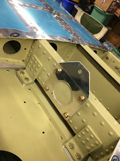
Then I bolted on the VS front spar mounting plate.  Amazing that this is all there is holding the VS front spar on the plane.

I then match reamed the top rear spar holes to the tailcone and installed the called out hardware.

Next I match reamed the lower holes and installed the called out hardware in the upper two.

Next I had to machine countersink the bottom holes to receive a flush head structural screw.

Here are the lower hardware in place.

Next I used the rudder hinge bracket as a guide to drill a #30 pilot hole in the whole assembly.

Then I punched it up to #12 for the hardware.

Deburred both sides of the hole.  And installed the called out hardware.

Next I installed the VS front spar bolt.  It is subject to rotation so they have you use a castle nut and a bolt with a cotter pin hole.  I won't do that now since it all has to come apart anyway.

Inside shot of the rudder stop/hinge bracket hardware.  Not enough threads for me showing so I will either go with a thin washer or a longer bolt at final assembly.

A ton of work in this pic!

Monday, May 6, 2019

Mounting the empennage to the tail cone #1

 Got started today with deburring the VS to HS front spar mount.  I still can't believe that this is all there is that holds the VS's front spar to the plane.....  I also fabricated the HS stab front spar mount spacers per the plans.  I used the band saw to cut em out.

 Next I match reamed the VS front spar mount plate to the HS front spar with a #12 reamer.

Next I reamed the top bolt hole to 1/4" full size.

 Then I deburred all the holes.

 HS front spar hole deburring.

 The back side...

 Then I went ahead and started prepping for drilling the HS mount holes onto the tailcone.  I placed the HS on the tailcone with the spacers I fabricated.  I used some straps to ensure the whole thing remains level and can't fall over.